(under construction !!!)
Building your own LINN LP12 SONDEK clone - The DD12 DDDEK !
- A Fotostory -


Jump to the "Foto story"
Jump to "Measurements"
Jump to "Listening Impressions"
Introduction:
Next to the DDDAC, I still listen a lot to Vinyl... I have a nice old LINN LP12, with EKOS and LINGO (both the "old" nr1)
and a more then fantastic KANDID MC cartridge.
Reading forums and looking at Ebay, I was intrigued by all the available 3rd party LINN LP12 upgrades.
These are all kind of in the same direction as the (VERY expensive original LINN upgrades - DC motor - Aluminum sub chassis etc)
You can almost build your own turntable with these parts I thought... Would it really be an improvement over my good old LP12?
So, just for fun, I decided to build my own LP12 Clone with as much as possible 3rd party products
This is what I bought as "3rd party parts and sub assemblies":
- Ebay - LINN EKOS SE/1 tonearm - demo
- Ebay - LINN KANDID MC cartridge - demo (yes, another one... I need to be able to compare both turntables, right ? ;-)
- Ebay - LP12 plinth - a beautiful piano black version with wooden base plate 6mm
- Vinyl Passion - "Orpheus" Stainless steel top plate
- Vinyl Passion - Blue Spring suspension set
- Vinyl Passion - "Unity 1" sub chassis with aluminum arm board (kit 2)
- Vinyl Passion - Cross Brace
- Vinyl Passion - LINN belt and bearing oil
- Mober - DC Motor with power supply / control unit for 33 and 45 rpm
- Mober - Special Bearing
- Mober - Inner Plate (with messing inlay)
- Ebay - A beautiful piano black plinth
- Ebay - A used dust cover (original LINN)
- Ebay - A brand new Outer Platter + felt mat - nicely polished - not even sure it was original LINN or not...
- Ebay - Hinges for the dust cover
- Ebay - Tone Arm connector and some more stuff (WBT Cinch etc) to make a pure silver interlink
- Schaefer AG - I made two small aluminum shields with the "LINN DD DEK LOGO"
ok, not 100% 3rd party , haha, but there is no way around the EKOS arm and the KANDID cartridge of course!
Below is the full story of the construction... (Lots of scrolling to do !)

The Mober Bearing does not fit through the standard hole of the Cross Bar -
So I need to widen it up a bit, so it can fit through

AS you can see the edges need to be smoothed a bit

Now it fits nicely. No problem it is not perfectly round - It is all inside the box

This is the Vinylpassion sub chassis Unity two - highly precision machined !!

Here we need to mount the bearing. This is the bottom view

The screws are adjusted with exactly 3.5Nm (I read this in LINN Forums, so just followed this advice ;-)

This is how it looks from above

And this from below

The Vinylpassion "Orpheus" top plate - great finish

The screw set for the top plate - it is all very complete and excellent quality

Just a view of the working bench :-) Note the cotton gloves!

The long screws on the top plate (also Vinylpassion)where we will fix the Blue Springs later.
It is extremely important that the screws are exactly under a 90 degrees angle. If needed adjust them

A nice view on the stainless steel top plate, which has a great finish (wear cotton gloves to keep it that way ;-)
Later this will be mounted on the plinth

At this point the motor from the Mober SET will be mounted in the top plate

Be careful with the two screws - not to tight, so the rubber washers are only slightly squeezed

A good view to show what I mean with slightly squeezed

Hard to see, but this is the photodiode and sender to measure the speed of the platter (later more)

It should fit on the space where normally the belt guide is situated (which we do not need anymore.
But as you can see the fitting is not optimal; a screw of the motor is in the way, so need to fix that

You can see the small unit is not flat on the top plate

Easy to fix though :-)

Now it sits flat !

The special Blue Spring set from Vinylpassion (adverted as with anti-vibration coating)

Here we have to put in the grommets

As you can see it sticks out. - IMPORTANT (!!) -
Cut off what sticks out of the grommet,
otherwise you will not be able to set up the sub chassis correctly and get a good "bounce"
On a later point we will mount the springs and adjust for a nice bounce

This is how the tone arm is delivered - including all cables (no need for it) and tools (great!)

Interesting to know that Mr Boomer assembled my arm ;-)
CORRECTION, haha some one on the LINN forum pointed out it is Mrs Boomer - Sorry for that !

Bottom view...

Have a look at finish of the EKOS SE/1 arm... what a beauty, right?

Another perspective

The black ring goes onto the arm board and will hold the arm

In this hole it fits nicely and will be screwed TIGHTLY (no body building please)

I used the special crew driver delivered with arm and just screwed it "tight" without deforming the material...

How it looks like after the arm has been slid into the ring

At the side is a screw which holds the arm - Later when the cartridge is built in I will adjust the hight

I was lucky to find this 3rd party plinth in Ebay

Beautifully done piano black finish!

A 6mm thick MD bottom plate

I mounted some very simple aluminum chassis feet with a rubber ring - bought in Amazon

To be able to work on the turntable and also to adjust the sub chassis conveniently I built this simple rig

The feet can be adjusted in hight, so it easy to level the plinth, in exact 0 degree

This is how it looks with the turntable on top

With two of the longer screws, the top plate is mounted

Below this point is are the small wooden blocks where the cross bar rests on.
With the two screws the top plate get extra hold

This is critical! The corner of the top plate normally rattles. With this screw the plate is adjusted so,
that the rattle just stops.
do NOT screw this tight - just enough to stop the plate to rattle.
Otherwise you WILL bend the plate...

Here you see the inside and where this screw is tightened

Now it is time to slide in carefully (remove arm first) into place

The screws must sit nicely in the middle of the grommet to ensure a solid bounce

This is how it looks when everything has been done right

Place the springs on top and turn them around till they feel situated well

Add the top grommet and turn the whole thing a couple of times to make sure all sits well

Put the nylon nut on - make sure to not lubricate these

For starters turn the nuts like 5-10mm on the screw.
later these will be adjusted for a correct hight of the platter and nice bounce

The cross bar is now fixed on the two long screws and we use them also for the
grounding connections (I used red wires, why not? ;-)

Detailed view - IMPORTANT !! Do not tighten TOO strong, the screw will bend the top plate into the wooden support...
As you can see in the following pictures, I actually did (shame on me...)
It is not too bad, I noticed early enough
not to completely wreck the top plate. Hence my WARNING !!
I hope it will not just destroy the sound (just kidding -
It just looks bad...but no use buying a new top plate and start over again)

One of the screws from the arm board is longer and can be used for ground connection to the sub chassis
Good thinking on details from Vinylpassion !! well done - it is the details that tells you how "passionate" a developer is ;-)

Now this is the special inner platter developed by Edmund from Mober.
For existing LP12
the most simple upgrade... you just need to exchange the inner platter.

It fits very exact in the Mober bearing - It is clear that this has been developed as a set
please do (not) note the small dents where the screws actually bent into the wooden support (!) (grrrrr...)

Well, it does start to look like a turntable now, right?

Mober is delivering two (yes, details and good thinking) self adhesive tachometer tracker rings

It goes inside the platter and the control unit has 16 times per rotation to calculate the speed in RPM.
It was a bit carefully working to make sure the ring is nicely equally glued to
the platter and does not twist or bend somewhere

By the way, this outer platter has a much nicer finish than my old LP12 platter.
I must say, it fits VERY well to the rest of the parts :-)

Before adjusting the springs for perfect platter hight and bounce, all must be level at 0 degrees

Already looking very nice :-)

The hight of the platter should be roughly 3-4 mm above the top plate

A view below from the rig - enough room to adjust the springs
Watch a video on the bounce result

Time to get the Motor control wired up - the picture shows it all.
I make sure that the cables are not touching the motor housing to avoid vibrations being transduced vice versa

This is how the tacho sensor wires are connected (The color is also mentioned on the PCB - good think of Mober)

The Mober control unit is very nicely build and finished

At the inside a very professional look - The IC type numbers are scratched off to protect Edmund's IP ;-)
I did measurements on the PWM signal controlling the motor. It is ~ 380kHz, which is excellent -
the DC motor runs at ~ 1.8 Volt average.
For a 36 Volt motor this shows that it is used in a very low mechanical stress area

I always make my interlinks and cables myself - here are the parts for the tonearm connector

I used Silver Teflon flexible wire. This is very light and will NOT dampen or hinder the bounce when connected to the arm

Shielded with a very soft sleeve. Ground is only connected at the output side of the cable

Parts for the interlink to the Phono amplifier
100% silver wired - WBT Cinch connectors - nice sleeves :-)

I also prefer a cable where the two signals (positive and negative) are being run through twisted signal wires.
These twisted wires are shielded by the metal sleeve, which is connected to ground at the turntable side.
Much better -and for all much more QUIET - then the "normal" cinch cables,
where the negative signal from the cartridge is run through the ground shield !!

Shrink tube is holding everything together before soldering to the cinch connectors

Final result - I like how the WBT connectors are being screwed tight to the cinch inputs !

The Interlink cable is fixed very tightly to the chassis to avoid vibrations entering the arm.
The arm wires are floating freely - avoiding bounce impact and vibrations transduced to the arm

Another perspective - avoid the wiring touch the base plate or anything else (ok, arm is fine;-)

Time to mount the LINN KANDID cartridge. It is said this cartridge / tone arm combination is getting
the best out of both.
Best to take the arm of the chassis. This will avoid stress for the bearing whilst fiddling around.
On top, it is much easier like this

For starters connect the signal leads, otherwise there will be little room to get them on!
Thanks to the 3 screw connection, set up is dead easy... only tracking force and azimuth must be done

Nice view :-) At this point I only tightened the screw slightly as azimuth still needs to get adjusted

The tracking force can be measured with this little tool. I took 1,73 grams as mid point between the recommended range

I use this little level bubble to check if the face of the LP is indeed level
than I put it on top of the headshell and see if all is still leveled - it was (no surprise though ;-)
Be carefully though!! I bought 3 of them and only one was on level with my electronic level - so do not trust them un-checked!

The arm is back on and set tight when playing horizontally (the perspective of the photo is misleading a bit - it is 0° ....
also you need to adjust the hight of the arm lift... This will become apparent as you will not be able to drop it on the LP ;-)
On the Azimuth topic whole books are written I believe, so I will keep it short. The EKOS arm cannot be twisted to adjust azimuth
hence you need to tilt the cartridge if needed. Even though these cartridges are built with highest precision, the azimuth is never 0°
so just mounting it at 0° will work, but it will not be optimal - I could hear this after the adjustment on my old LP12 set up clearly.
There are many methods from which most are very crude; like measuring with a multi meter and adjust for channel balance only.
It turns out, that actually the phase correlation is much more important and audible, but this requires more sophisticated equipment...
I am using the Feickert "Adjust +" software. The end result was that I needed to tilt the Cartridge 1° to the left for optimum result.
Very simply done by adding a small hard-paper washer between cartridge and head shell.

It becomes apparent, that when you do NOT adjust azimuth you are losing correct phase AND like 5dB Channel separation!
By the way these values with 35dB channel separation are just awesome... :-)

text for the above image

text for the above image

text for the above image
Jump to the top of this page"
Measurements to compare the "old" LP12 and the "new" DD12 DDDEK !
OLD VERSION

Rumble Test of the "old" version with Arm up and down in silent groove

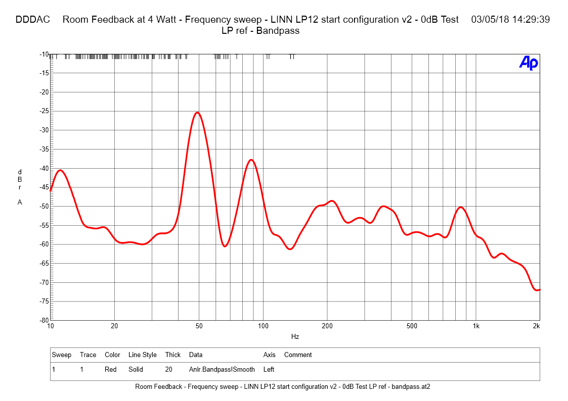
Room Feedback (4Watt power level) with arm down - platter not spinning

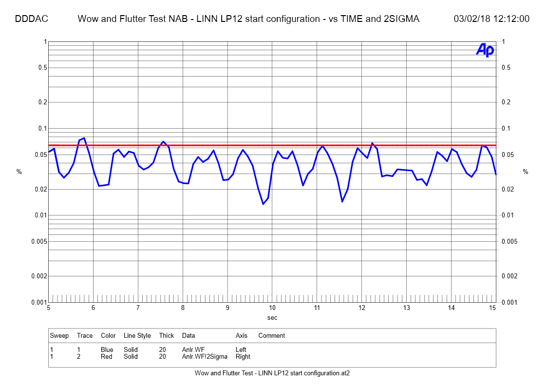
Wow and Flutter Test - Time NAB

Wow and Flutter Test - FFT
NEW VERSION
to be completed
Jump to the top of this page"
Listening impressions, comparing the "old" LP12 and the DD12 DDDEK !
Here comes the text for the listening impressions
Jump to the top of this page"
|