A S/PDIF solution for the DDDAC1794
There was still a lot of request for good old S/PDIF, so I designed a "S" version...
I assumed high res audio was only about PC and Mac, so I never bothered to implement S/PDIF right in the beginning. But
I learned that there are still quite some CD Players in use or other media players (or PCs which use S/PDIF output).
As S/PDIF is not that difficult to implement, I took this up and started designing again.
As you know the KIT is already available for some time. I just had no time to update the Web Site ;-)
These were the design requirements I wanted to implement in the new mainboard:
- It needed to be fully compatible with the "USB only mainboard" and the DAC Modules, electrically and mechanically
- The S/PDIF functionality
- Use best available technology (is a bit arbitrary of course ;-)
- Sampling rates Up to 192kHz (Optical 96kHz)
- Option for a 12MHz XO Clock (like the ones from Guido Tent)
- Easy to switch between USB and S/PDIF source
- Improve a few things on top:
- LED signal part can be broken off for use at the front panel of the chassis
- Improve buffering of signals to be able to drive more boards (so far 11 is done)
- Improve timing of I2S signals with flip flop in stead of the 1k resistor solution for data-delay
- Make logic voltage 5 Volt for higher compatibility inside the design
The only important selection was the receiver itself.... There are a few choices, like DIR9000 CS8416 and the Wolfson WM8804.
I have been listening around and for arbitrary reasons, I thought the Wolfson WM8804 would be the best choice for me.
I bought a few chips, made some breadboard tests and voila it woked within a few weeks. Let me explain a few things I did in the new mainboard...
You can download the full schematics (S/PDIF and USB mainboard version) from the download section or push the button below:

Theory of operation of the S/PDIF mainboard
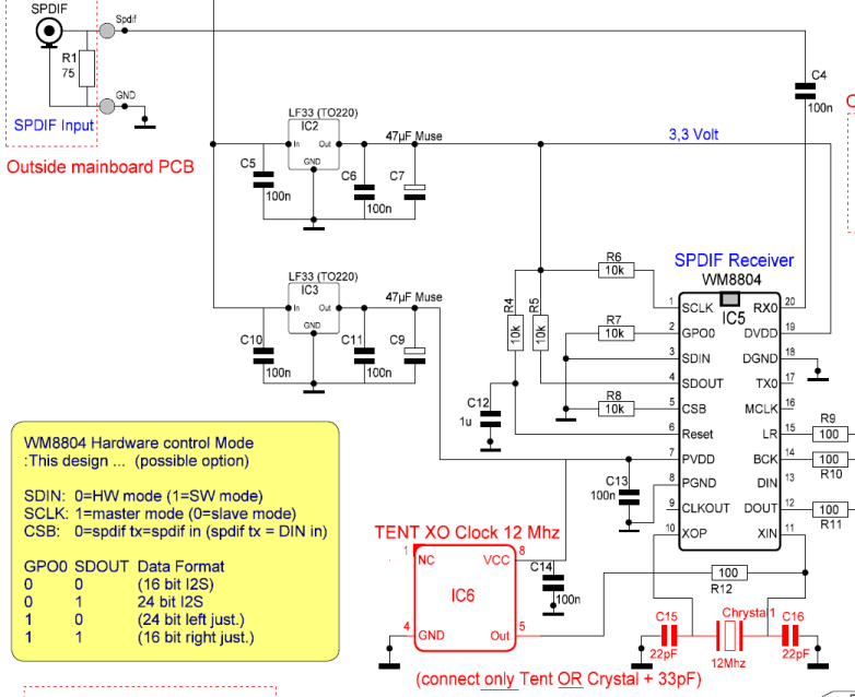
First part was the implementation of the WM8804. It is done of course in hardware mode. In the schematic below you recognize the option
for the XO clock. Further more there is a set of resistors, which are used to configure the WM8804 at start up. Of course I need to Wolfson chip
to output I2S signals based on S/PDIF input signal. All easy, after studying the somewhat complex data sheet.....
In the circuit clip below you see I have chosen to separate the power supplies for the chip to maximize performance.
In case of a Tent Clock installed, the two ceramic Cs and Crystal should be removed (or not installed). The 75 Ohm resistor (R1) is not on the mainboard.
It is meant to close the impedance of the coax cable, so best position is directly at the RCA connector...
176.4 kHz Operation Note
One thing to keep in mind please: according to design (and datasheet) the WM8804 does not distinguish between 192 and 176.4 kHz in hardware more,
So it will not correctly lock onto 176.4 kHz unless you operate it in software mode. So this mode will not work.
Normally this should be no issue as most spdif outputs are coming with 44.1, 48 96 or 192...

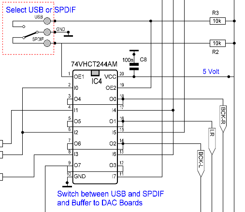
I had two problems which needed to be solved: First.... The WM8804 is outputting 3,3 Volt logic and I wanted to control the
DAC boards (and WaveIO) with 5 Volt logic. Secondly I wanted to be able to switch between USB (WaveIO I2S signal) and the S/PDIF I2S signal.
After some reading and checking I came up with the following solution. The 74VCHT244 is a bus buffer which converts 3-5 Volt logic to 5 Volt logic.
As it can go in tri-state (high impedance on the bus) I saw a kind of two way switch in front of me :-) Have a look at the circuit clip below and
you will understand the beauty of this solution.....
- The inputs are switched without use of mechanical switches
- The strong output buffers can have the clock signal drive more DAC boards (the USB only board can do max 4 DAC modules)
- All is 5 Volt logic now at the output

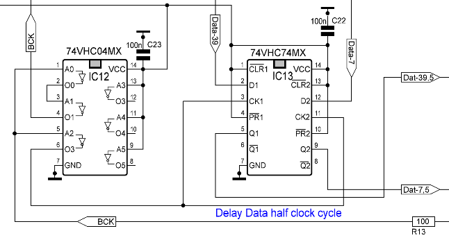
The final difference with the USB only mainboard is the improved data delay. Remember? The Data needed to be delayed half a clock cycle.
I did that with a 1k Ohm resistor at the data input. I was not sure how well this worked at multiple boards (now 11 have been tried ;-)
so as I was designing, I simply implemented a standard flip flop to delay the data signal with an extra half cycle.
This means, that when data is being clocked into the DAC, the state is rock solid at clock transition...

 |
The Board itself
Compared to the "red USB only board, you can easily recognize the section, where the WM8804 chip is and the extra power supplies (3,3 volt)
At the Left is now the connection for the LED indicators. It can be easily broken off for front panel use, or just let it stick of course
This example shows a 4 deck version. Several 8 Decks have been implemented without any drive issues. I know of two cases where 11 boards were stacked with great success !
As mentioned, the board is fully compatible with the old DAC boards, as well the somewhat revised second version of the DAC module, which is now being delivered.
You can freely use them through each other. So easy of DIY is guaranteed :-)
|
The DDDAC1794S
Next to S/PDIF functionality, several practical improvements
|
Keep reading ...... the story continuous with installing all software ( Programs and Drivers )
|