Final Test Results and Specifications
Some background
Most of audio DIY are using mostly their ears to design and tweak their sound equipment. A very valid way of doing things, as
it leads to results for the joy of our ears and not for the joy of datasheets or great looking specs (what ever that is ... ;-)
nevertheless, I am a bit more engineer than that and I want to make sure I find correlation between the technical specs and
what I have been experiencing. I see this as the only way to further develop and enhance my designs.
I also want to publish my results, so some one who actually builds my design, has a
reference to see if things worked out fine. On top, I am sure many readers just want to know what the DDDAC1794 NOS really can do ;-)
I have been doing all my testing with a digital oscilloscope with built in FFT analyzer (Velleman). Even though this small system is very use- and helpful, the resolution and
quality of the measurements are negatively impacted by the limited bit depth. Only 8 bits... And of course all other electronics as well.
The problem I see, is that there is hardly
anything in between hobby T&M equipment and the professional gear. Well I have good news. Today I (finally) bought an AP System 2 with all options
so soon I will be able to replace these by real professional measurement results :-) But for now these will do as well....
More background...
It took quite some years (of saving), but finally I have been able to buy new test equipment. I was lucky to find a very nice refurbished AP system 2 (SYS-2322)
and also the serial interface SIA-2322. With the latter I can use all generator and sweep signals directly in I2S format! It is a real dream machine and hence the complexity,
it took me some time to come up with the first nice measurements.... From now one I will mostly use the AP for my measurements :-)
New Measurements with AP System 2 (SYS-2322)
 |
Linearity test
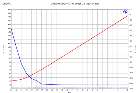
For a DAC, I would state, the linearity is among the most important measurements. The question is, if that what you see, is actually what you get?
Like when the datasheet says it is 24 bits, does it really convert those bits correctly? Normally this is not the case. The datasheets are also normally not very helpful.
Dynamic range, which is stated normally, is very theoretical and does not say a single thing about how GOOD the DAC is at the lowest bits... So lets see what my DAC does!
The linearity test is a standard measurement coming with the Audio Precision analyzer. It sweeps the signal from high (0dB) till lowest possible and the output is measured.
We expect a linear curve of course. Believe me, most DACs are getting pretty messed up at anything below 100dB or even 16 bits. Not this set up! I was a bit surprised my self
to be very honest. What I like most, is that the deviation from a straight line is very smooth and in the very last bits (bit 23 = 24th bit)the signal smoothly sinks away in
the quantization noise... I am pretty proud on this one :-)
|
Linearity test:
Extremely linear behaviour! Also nice to see, that below 21 bits things get fuzzy...
|
Quantization noise floor
Now this is some interesting stuff. Whether we like it or not, the PCM1794 is not a R2R DAC. Actually a kind of mix between multi bit and 1-bit...
Meaning there will be a conversion from bit stream to parallel data so to speak.
I had some remarks in the beginning, that by using the bit clock (BCK) for the system clock as well,
the quantization noise would be totally ruining the performance. Well, I know this is not the case, as it sounds terrific. But still I was intrigued on the subject, so I
decided to run some tests on the noise floor when the DAC is active. I send a 20Hz test tone of less than -100dB to the DAC, so it will stay out of the noise band and
measure the actual residue above 1kHz
In the image you can see the noise floor on 3 major sample frequencies and the effect is noticeable. Even at CD format absolutely acceptable.
On 192kHz, as expected, the effects are outside the audio band |
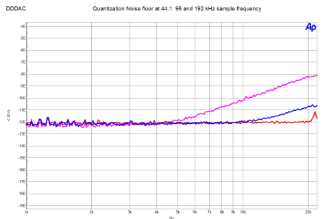 |
Quantization noise floor:
Clearly to see, that with low sample frequency (44.1kHz), the quantization noise kicks in in the audio band. Never the less low enough :-)
|
Below here, the "old" measurements:
Capacitor coupled output measurements:
 |
Sinewave 1kHz
Classical start of the measurement, what does a 1kHz sinewave look like? Well, it looks very good
thanks to sample frequency Fs of 192kHz. Very few recognizable steps. The output voltage is 1,2 Volt RMS.
At the right bottom you will find the Voltage in dBm. Which is 3,7dB... So now lets have a look at the low and high end of the spectrum --->
|
Capacitor Output:
1kHz sinewave, producing smooth signal at 1,2V RMS
|
Sinewave 2Hz
Here you see clearly, there is only a drop of 0,5dB (3,7dBm - 3,2dBm) at 2Hz. Wow, that goes deep enough.
Please do not forget, the "internal" load of the DAC are the bleeder resistors of 100k. Therefore
if you have a proceeding amplifier stage with significant lower input impedance, you need to check the
output section for the table of cut off frequencies. Anyway, there is no discussion on the low side of things
|
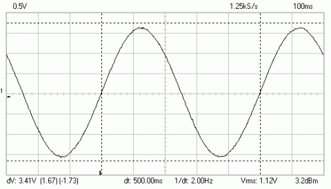 |
Capacitor Output:
Only -0,5dB loss at 2 Hz with 100k Load...
|
 |
Sinewave 10kHz
This looks like rubbish, but everyone who knows what a NOS DACs does to 10kHz signals with Fs of 44.1kHz will only smile :-)
This shows clearly, that at high frequencies the HD signals (and also sound) are benefiting from the
extra samples you have (x 4). You might argue, oversampling does 8 times... Yes, but it does a
lot more, namely making up samples which never existed before. No, this is what you want!
|
Capacitor Output:
Finally a 10kHz signal from a NOS DAC which looks like a sinewave and not like a damaged square wave ;-)
|
Squarewave 1kHz
Now we speak business, show me the DAC with digital filtering which can do this.... and if not convinced see
the other four images below ....
|
 |
Capacitor Output:
True square wave reproduction of 1kHz
|
 |
Squarewave 12kHz
So this is 12kHz.....
|
Capacitor Output:
True square wave reproduction of 12kHz
|
Squarewave 48kHz
and here we have 48kHz...
|
 |
Capacitor Output:
True square wave reproduction of 48kHz
|
 |
Squarewave 96kHz
I admit, that for example 95kHz would not work, as this would not be sampled well. It would be too close to half of Fs.
But the 96kHz on itself just shows how fast the DAC is and that
the NOS does its work (or basically does not do any filtering work... so nothing = better :-)
|
Capacitor Output:
Of course not needed in audio, but a 96kHz square wave coming from a DAC is always nice to look at
|
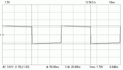 |
Squarewave 20Hz
A very special case. The top of the square wave is a straight line. When it would be 100% flat it would be DC, or 0Hz.
Of course that is impossible, but if it comes close, it shows the output can go very low. As described before the low
frequency cut off is indeed very low, so therefore you see the top almost flat and hence an almost perfect square at 20Hz...
|
Capacitor Output:
20 Hertz (!) Square wave showing the good low frequency performance with capacitor output
|
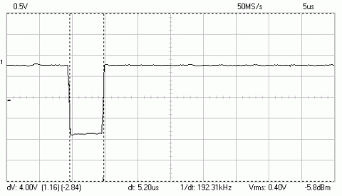
One pulse 192kHz
If you measure the one pulse signal coming from a normal DAC with digital filter, you get the typical wave form
where a sinus is ringing in, than has a peak and than start ringing out again.
All several periods long = f(x) = sin(x) / x. This diffuses the sound stage I believe, hence a NOS DAC is so nicely direct and spatial...
|
 |
Capacitor Output:
A one shot pulse = a pulse and not a sin(x) / x function
|
 |
FFT Sinewave 100Hz
No measurement without a FFT graph :-) This is the frequency spectrum of a sine wave of 100Hz. Normally you do 1kHz,
but my measurement system has (hobby) limitations, hence I take the 100Hz. This shows that there is no problem at all with too high distortion
by using a passive I/V conversion. As you can see it is mostly second harmonic ( d2 ) and only 0,4% (-56dB. Of course measured with FULL scale
signal 0dB ! Here there is high reward for using 8 Volts for the analog section of the PCM1794....
|
Capacitor Output:
True square wave reproduction of 96kHz
|
Bandwidth - 96kHz
As expected, straight line till -3dB point where Fs is. Mathematically correct and allowing for a great sound reproduction.
|
 |
Capacitor Output:
Transfer of the DAC: -3dB roll off as expected at 96kHz
|
Transformer coupled output measurements:
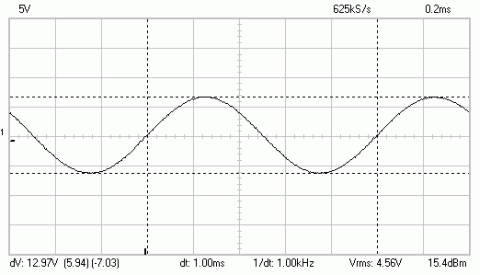 |
Sinewave 1kHz
similar comments as with the capacitor. But with more Voltage output. 4,56V RMS Output from a DAC without any active
elements and with this bandwidth is just awesome. Great job from Brian Sowter :-)
|
Balanced Transformer Output:
4,56Volt RMS Output !
|
Sinewave 10kHz
You can see that on one hand the signal smooths out a bit thanks to the HF roll of function of the transformer. Also that there is small overshoot
at the edges. The transformer is loaded with 10kOhm internally. It could be dampened more, but the overshoot frequency is so high, it does not disturb. Further
to be noticed, that at this output we only have a loss of 0,2dB!
|
 |
Balanced Transformer Output:
10kHz 4,44 Volt output, only a loss of 0,2dB
|
 |
Sinewave 25Hz
25Hz with -1dB and only 0,5% d3 is absolutely top of the bill. 15Hz is -3dB and at 8Hz you will finally find -6dB point. Okay, with a whopping 5% d3,
but show the speakers who can actually do this. It is more important, that this is away from the useful audio band.
|
Balanced Transformer Output:
25Hz, only 0,5% distortion! And that with only 1dB signal loss...
|
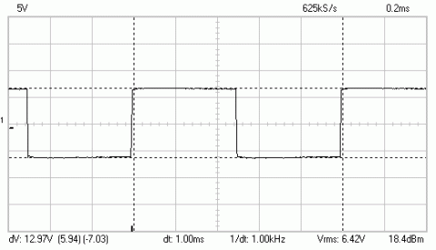
Squarewave 1kHz
Such a signal form coming out of a transformer, who would have thought that. This is really GOOD!
|
 |
Balanced Transformer Output:
1kHz output, perfect square wave
|
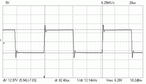 |
Squarewave 12kHz
Now we see some overshoot, but remember this is already a 12kHz square wave!
|
Balanced Transformer Output:
Very good result at 12kHz with some overshoot
|
One Pulse 192kHz
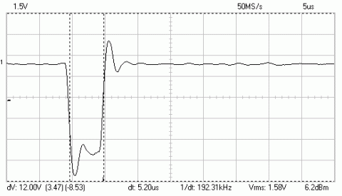
For a transformer this is hell... The overshoot is noticeable. But if you see that this is only half of the pulse width,
than you can calculate the frequency of the swing is approximately 400kHz. This will not interfere with your listening experience.
On the contrary, it enables a fast transparent sound and brilliant highs, specially for a transformer output.
|
 |
Balanced Transformer Output:
Prefect response on 192kHz. The swing is far outside the audio band with 400kHz
|
 |
FFT Sinewave 100Hz
The balanced output is paying off... hardly any d2 visible. So now the d3 is left over with a very low value of only -63dB,
which equals 0,07% distortion
|
Balanced Transformer Output:
Only 0,07% d3 left over! The balanced output is canceling out the d2 distortion almost completely
|
Bandwidth 96kHz
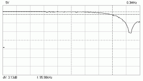
The transformer, we know that from the output section, has a very high bandwidth, which goes far beyond 200kHz. What
you see here is the limitation of the DAC sampling frequency, limiting it at -3dB at half of Fs. The rest of the transfer is
a prefect straight line.
|
 |
Balanced Transformer Output:
Perfect result. The transformers limitation are way beyond the digital HF roll off (The known 1/2 Fs theory)
|
DDDAC Power supply
 |
Power Supply (hf) noise
For me the most important measurement was to check on the design goal of having low noise.
The noise coming out of the power supply is mostly a HF component of 12Mhz, which is the resonance frequency of the control loop.
This shows the power supply is very fast and generates noise far outside the audio band. On top it is ONLY 0,74mV ...
Important note: This is measured under real working condition! DAC Attached....
|
Power supply Output:
Very quiet output from the Power supply (0,74mV). This is measured under real working condition
|
Final specifications (updated 2023)
with 2,2uF capacitor coupled output:
- Output = 1,2V RMS at 1kHz sinewave 0dB signal level
- Bandwidth (-3dB) = <1Hz - 192kHz
- LF Signal distortion at 0dB signal level d2=0,4%
- Output impedance per Deck = 133 Ohm (reduces proportionally by number of decks)
- Maximum Fs = 384kHz at 24 bit resolution
- No digital filter (allowing for 192kHz square wave reproduction)
- Power consumption 12Volt: Mainboard = max 60mA
- Power consumption first generation DAC Module (pro deck) max 100mA
- Power consumption second generation "powered by Tent" DAC Module (pro deck) max 250mA
- Power consumption 5Volt: USB WaveIO = 385mA
with Sowter 1:2 balanced transformer:
- Output = 4,6V RMS at 1kHz sinewave 0dB signal level
- Bandwidth (-3dB) = 15Hz - 192kHz
- LF signal distortion at 0dB signal level d3=0,07%
- Output impedance with 4 Decks = 270 Ohm
- Maximum Fs = 384kHz at 24 bit resolution
- No digital filter (allowing for 192kHz square wave reproduction)
- Power consumption 12Volt: Mainboard = max 60mA
- Power consumption first generation DAC Module (pro deck) max 100mA
- Power consumption second generation "powered by Tent" DAC Module (pro deck) max 250mA
- Power consumption 5Volt: USB WaveIO = 385mA
I have made some drawings of the boards and their dimensions when stacked(push the button below to download pdf file:)

Keep reading ...... the story continuous with other related projects ( Other Projects )
|